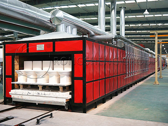
The grid design is a crucial aspect of the overall glass melting furnace design. A well-designed grid can significantly increase the preheating temperature of the combustion air, resulting in higher combustion temperatures for the fuel and thus contributing to combustion and heating throughout the furnace. It also allows for greater recovery of waste heat from flue gas and lower exhaust gas temperatures. Furthermore, it reduces the volume of combustion exhaust gas, thereby decreasing emissions of harmful substances such as nitrogen oxides, sulfur and its oxides, and particulate matter, resulting in a significant environmental protection benefit.
Basic Information on the Regenerator Chamber Checkerboard Structure
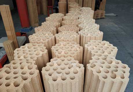
The checker brick structure of the glass melting furnace regenerator chamber is constructed using standard checkerboard bricks. These bricks are uniform in size, inexpensive, and have a short delivery time. The refractory material used to produce the checkerboard bricks should have high density and high thermal conductivity to ensure sufficient heat storage and exchange capacity. Setting the preheating temperature of the combustion air and the exhaust gas temperature are crucial prerequisites for checkerboard design.
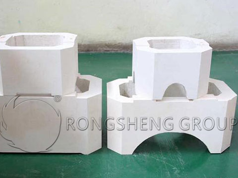
The function of the regenerator chamber is to exchange the waste heat from the flue gas discharged from the melting zone of the glass melting furnace with the combustion air, thus recovering waste heat. The type of checkerboard bricks, their arrangement, the size of the checkerboard pores, the wall thickness (brick thickness), and the material of the checkerboard bricks all affect the heat transfer performance of the checkerboard structure. The type of fuel plays a significant role in flue gas radiation and is also a factor affecting the heat transfer performance of the checkerboard structure.
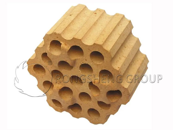
From a thermal engineering perspective, the size of the checkerboard pores directly affects heat exchange; smaller pore sizes result in a larger unit heated area and greater heat exchange capacity. However, from an operational perspective, smaller apertures increase gas flow resistance, and the likelihood of blockage due to ultrafine powders in the batch or dripping slag also increases, which affects the heat exchange capacity of the lattice.
Operating Conditions of the Regenerator Chamber in a Glass Melting Furnace
The operating conditions in the regenerator chamber of a glass melting furnace are extremely harsh. It must withstand the erosion of high-temperature alkaline vapors, flue gas, and various solid fly particles, as well as the thermal shocks caused by the reversal of combustion air and flue gas. The lower bricks also bear the heavy pressure from the upper bricks. The conditions can be broadly categorized as follows:
- ① Gas erosion from high-temperature alkaline vapors and flue gas;
- ② Solid erosion from acidic and alkaline dust fly particles in the batch materials, and harmful impurities in the fuel;
- ③ Liquid erosion from liquid sulfates in the condensation zone;
- ④ Structural and thermal stresses caused by alternating temperature changes during reversal, leading to fatigue failure of the bricks;
- ⑤ Chemical reactions in oxidizing and reducing atmospheres damage the structure and crystal phases of the bricks;
- ⑥ The lower bricks bear the heavy pressure from the upper bricks, generating significant compressive stress.
Support Layer for the Grate Structure
The regenerator grate structure cannot be directly built onto the leveling bricks of the grate arch because the center-line spacing between adjacent grate arches in the transverse direction is twice the grate module, while the width of the grate arch is only 150mm. The spacing between these grate arches generally exceeds the external dimensions of the grate bricks, and a single grate arch cannot directly support two rows of grate bricks simultaneously. Therefore, a layer of grate support bricks is used for transition. Structurally, this is equivalent to adding a transition beam above two adjacent grate arches. Only on top of the support bricks can the grate bricks be laid according to the grate module.
The grate support bricks are inverted U-shaped with retaining brackets at both ends. The upper length of the support brick is approximately twice the grate module, and the lower retaining bracket length is approximately the spacing between two grate arches. The support bricks should be evenly stacked above the leveling layer of the grate arch according to the grid module dimensions. This not only fixes adjacent grate arches at intervals of the support platform length, but also creates a stacking platform on the top surface of the support bricks that is suitable for the grid module.
The upper length of the inverted U-shaped support brick of the grid should be slightly smaller than twice the grid module dimension to account for thermal expansion; generally, a 5mm gap dimension needs to be subtracted. The support bricks near the inner and outer walls have different support platform dimensions at both ends, and their brick lengths also differ slightly, requiring design adjustments based on specific circumstances. The height dimension of the regenerator grid includes the height dimension of the support layer.
Aperture Dimensions of the Regenerator Grate in a Glass Melting Furnace
To achieve the set preheating temperature of the combustion air, the regenerator chamber of a glass melting furnace must have a suitable grate volume and heat exchange area. The aperture size of the grate plays a crucial role in the volume, length, width, and height of the grate, and also significantly affects its heat exchange efficiency.
Based on the actual situation of high ultrafine powder content in domestic glass batches, the aperture size of the regenerator grate should be 150–170 mm. Most domestic glass melting furnaces actually use a grate aperture of 160 mm for cylindrical bricks and 165 mm for strip bricks; this is a value derived from long-term production practice and optimization.
Simplified Formula for Regenerator Grate Design
Although the heat transfer in a glass melting furnace regenerator is unstable, the total heat released by the flue gas and the total heat absorbed by the combustion air in each switching cycle are essentially stable. Therefore, this stable total heat transfer should be expressible by the formula: Heat Transfer = Heat Transfer Coefficient × Heat Transfer Area × Temperature Difference. Based on the required preheating temperature of the combustion air, the total heat transfer required for the glass melting furnace can be calculated through the heat balance of the lattice. If the overall heat transfer coefficient of the lattice (unit: kcal/(m²·cycle·℃)) and the logarithmic mean temperature difference between the flue gas and the combustion air can be calculated, the required total heat transfer area of the lattice can be determined, and thus the volume of the lattice can be calculated, making the lattice design easy.
Materials Selection for Commonly Used Lattice Bricks in Glass Melting Furnace Regenerators
Alkaline bricks used as lattice materials have a large heat storage capacity and strong heat exchange capacity. Since the 1950s, alkaline refractories have been used in glass melting furnace regenerators abroad and were gradually adopted in China in the 1980s. Different refractory materials are selected based on the different temperatures in different height areas of the lattice, the amount of dust and fly ash in the flue gas, and the periodic temperature changes.
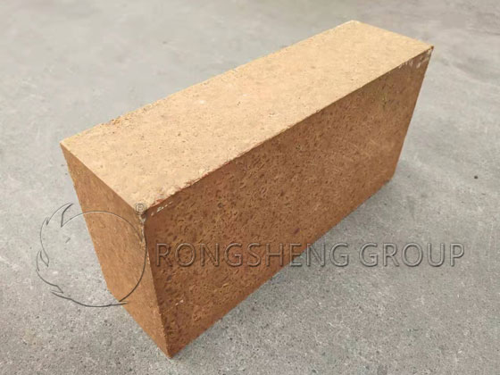
Alkaline bricks meet the increasingly stringent requirements of glass melting furnace regenerators, leading to their widespread adoption in recent years. In the high-temperature zone (1100–1450℃) of the grid structure, low-iron fired magnesia bricks with good stacking structure are used; the domestic brand is DMZ-97 fused magnesia brick.
In the mid-temperature zone (800–1100℃) of the grid structure, the magnesia bricks are subject to significant chemical erosion by alkaline sulfates and SO3. Changes begin on the brick surface, with MgO and CaO diffusing or volatilizing. This erosion reduces the brick wall thickness, potentially jeopardizing the grid’s stability. In the upper half of this temperature range, domestically produced DMZ-95 fused magnesia bricks can be used; in the lower half, domestically produced DMC-12 direct-bonded magnesia-chrome bricks can be used.
In the low-temperature zone (below 800℃) of the lattice, low-porosity clay bricks (ZGN-42 bricks, 42% Al2O3) with good resistance to thermal shock were used and performed well.