Mechanical grate incinerators offer high processing capacity and strong adaptability to various types of waste. However, the designs for these incinerators often involve a wide array of refractory brick specifications—sometimes numbering in the hundreds. Even for the same type of grate incinerator, designs from different boiler manufacturers require different brick configurations. Rongsheng Refractory Factory: refractory materials for grate-type garbage incinerators. Free Quote Now!
This lack of standardization in refractory brick specifications and dimensions complicates production, drives up costs, extends lead times for stocking, and renders the bricks non-interchangeable. On-site installation is slow and prone to masonry errors, further delaying project timelines. Moreover, maintenance during operation is difficult, time-consuming, and costly. To ensure that refractory bricks can be used universally across different incinerator models, the existing brick designs have been optimized for size and structure, resulting in a more versatile solution with enhanced adaptability and broader compatibility.
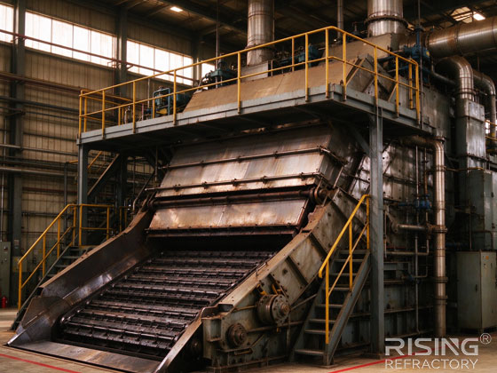
Optimization of Refractory Brick Design for Grate-Fired Furnaces
Currently, furnace lining structures are primarily categorized into air-cooled walls and thermally insulated (adiabatic) walls; water-cooled walls generally do not utilize refractory bricks. Typically, lightweight materials are used for the thermal insulation and heat-retention layers, while heavy-duty refractory bricks are reserved for the working (hot-face) layer. The thickness of this working layer ranges from a minimum of 114 mm to a maximum of 230 mm. For vertical structures—such as drop-off walls, side walls, and rear walls—the masonry consists mainly of standard rectangular bricks and tie bricks (used to anchor the vertical walls). In areas where the base (footing) is inclined, specialized base-leveling bricks are required to establish a horizontal surface. When air-cooled walls are employed, if the heated air is directed into the furnace as secondary combustion air, specific air-outlet bricks must be used. For embedded-style air-cooled walls, the grate frame requires the use of integrated air-cooling bricks. Furthermore, monolithic (unshaped) linings—often found on side walls or furnace roofs—require the inclusion of dedicated anchor bricks.
The working linings of grate-fired furnaces remain predominantly brick-based. Although the various brick types used in these furnaces lack universal interchangeability and vary significantly in quantity, they can be classified according to their functional roles. These include standard rectangular bricks, tie bricks, integrated air-cooling bricks, drop-off wall cap bricks, base-leveling bricks, air-outlet bricks, and anchor bricks. Side wall masonry primarily utilizes standard rectangular and tie bricks, while the other types serve specialized functions. Consequently, categorizing, summarizing, and optimizing these brick designs can enhance both their simplicity and their versatility.
Optimization of Refractory Brick Shapes
The refractory bricks used in the working lining of a grate-fired furnace can be optimized into three main categories: rectangular bricks, interlocking/anchoring bricks, and specialized bricks. Vertical walls utilize rectangular bricks and interlocking/anchoring bricks. Air-cooled furnace walls employ embedded air-cooled bricks; the tops of stepped walls use dedicated top-cap bricks; the base sections of the furnace frame use base-support bricks; air-cooled wall outlets use specialized outlet bricks; and monolithic (unshaped) linings utilize anchoring bricks.
2.1 Rectangular Bricks
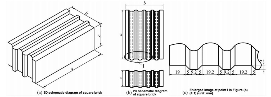
Rectangular bricks are straight-shaped bricks featuring a tongue-and-groove (protrusion/recess) design. They primarily consist of main bricks, joint-adjustment bricks, and end-plug bricks (see Figure 1). Main bricks form the bulk of the furnace lining, while joint-adjustment bricks are used to manage the positioning of brick joints. End-plug bricks are designed to seal off sections of the air-cooled furnace wall structure.
These rectangular bricks are categorized into two series based on length: a full-length brick (230 mm) and a half-length brick (114 mm)—the latter being used to create staggered joints between layers of refractory brick. Within each series, the bricks are further divided into five groups based on the effective working thickness of the lining: 115 mm, 150 mm, 176 mm, 200 mm, and 230 mm. This range accommodates the construction requirements for furnace walls across grate-fired units of varying capacities.
Compared to traditional straight-shaped bricks, these optimized rectangular bricks offer the following advantages:
- 1) The tongue-and-groove (protrusion/recess) design enhances the self-anchoring capability of the furnace wall. This not only resists sliding caused by the pressure of waste material but also effectively mitigates the risk of the wall bulging or collapsing due to high-temperature thermal stress.
- 2) When laid using high-temperature mortar, this brick design provides superior sealing, effectively preventing hot flue gases from escaping through the brick joints.
2.2 Anchoring Bricks
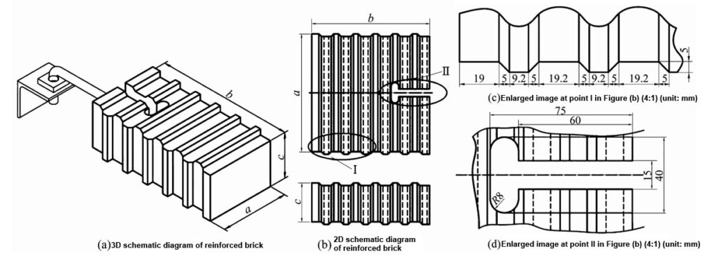
Anchoring bricks are specially shaped bricks used to secure vertical furnace walls. Their interlocking (tongue-and-groove) sections are embedded within the rectangular refractory bricks, while their tail ends feature slots for anchoring. The outer ends are secured (or connected) to the furnace shell’s steel structure using metal anchors; see Figure 2 for a schematic. Based on the required lining thickness, these anchoring bricks are categorized into five types: 175 mm, 210 mm, 236 mm, 260 mm, and 290 mm.
Compared to traditional anchoring bricks, this tongue-and-groove design provides the same functional benefits as the aforementioned rectangular bricks. Furthermore, the design of the anchoring mechanism ensures high holding strength while facilitating ease of installation. It also serves to protect the anchoring components from corrosion caused by flue gases.
2.3 Inlaid Air-Cooled Bricks
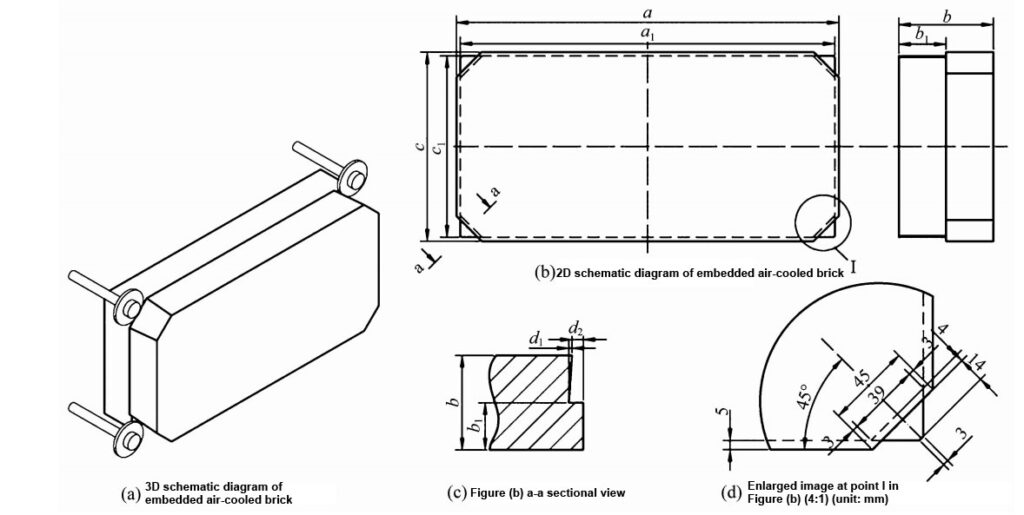
Inlaid air-cooled bricks are specially shaped bricks embedded into the hot face of air-cooled furnace walls. Their outer ends are secured to the furnace shell’s steel structure using bolts or side-mounted retaining rings; see Figure 3 for a schematic. A single, standardized brick design is used for these inlaid air-cooled components.
2.4 Top Bricks for Drop-Wall Sections
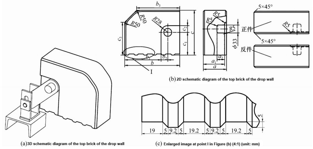
Incinerator grate systems are typically arranged in multiple stages, with “drops” (vertical offsets) between each stage. These drop-walls are constructed from refractory bricks, providing both thermal insulation and wear resistance. The top bricks for these drop-walls are specially shaped units designed for the uppermost section of the wall. Their bottom surfaces feature a tongue-and-groove (interlocking) structure, while the top, left, and right surfaces are flat—with one surface transitioning into an adjacent side via a curved connection. The rear portions of the left and right sides contain holes for anchoring, and the outer ends are secured (or connected) to the furnace shell’s steel structure via metal anchors; see Figure 4 for a schematic. Typically, a single course of 230 mm thick bricks is used for the top of these drop-walls. As waste tumbles and falls, it exerts pressure on the refractory brickwork of the drop-wall. A tongue-and-groove (protrusion/recess) design is employed to stabilize the furnace wall while simultaneously preventing the leakage of flue gases.
2.5 Base-anchor bricks (Footing bricks)
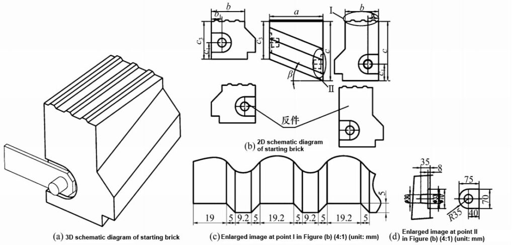
Base-anchor bricks are specially shaped bricks used at the junction between the side walls and the grate frame. Their bottom surfaces interface with the grate frame, while their top surfaces feature a tongue-and-groove (protrusion/recess) design. The side faces include holes for securing, and the outer end is fixed (or connected) to the furnace shell’s steel structure via metal anchors. See Figure 5 for a schematic.
The base-anchor bricks for the left and right side walls are symmetrical (mirror images of each other). The upper section utilizes a mortise-and-tenon-style interlocking design. Based on common grate frame angles, these bricks are categorized into three series: 15°, 21°, and 25°. Within each series, the bricks are further divided into five types based on the effective working lining thickness: 125, 160, 186, 210, and 240 mm.
2.6 Air-outlet bricks
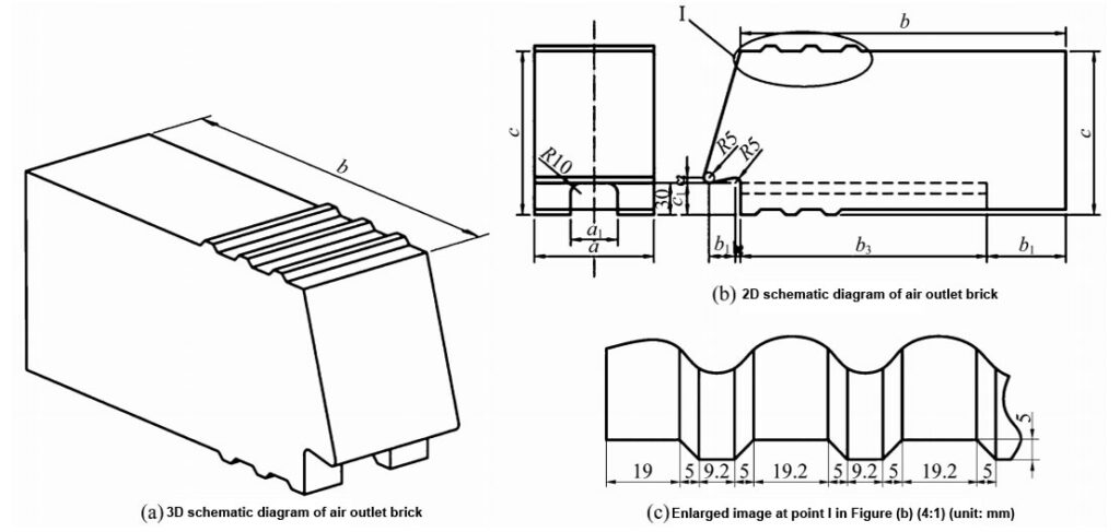
Air-outlet bricks are specially shaped bricks designed to channel heated air from an air-cooled furnace wall into the interior of a grate-fired furnace. Their top and bottom surfaces feature a tongue-and-groove (protrusion/recess) design, while the side faces are flat. The bottom surface includes a U-shaped groove for directing the airflow. See Figure 6 for a schematic. Air-outlet bricks are categorized into five types based on the effective working lining thickness: 250, 285, 311, 335, and 365 mm.
2.7 Anchoring bricks
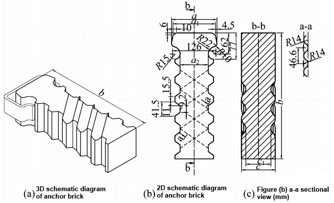
These are specially shaped bricks used to anchor monolithic (unshaped) refractory materials. The tongue-and-groove (protrusion/recess) portion is embedded within the monolithic lining, while the outer end is fixed (or connected) to the furnace shell’s steel structure via metal anchors. See Figure 7 for a schematic. Based on the thickness of the furnace wall, anchoring bricks are categorized into fifteen types, with dimensions of 150, 175, 200, 225, 250, 275, 300, 325, 350, 375, 400, 425, 450, 475, and 500 mm.
Modular Design and Practical Application of Furnace Walls
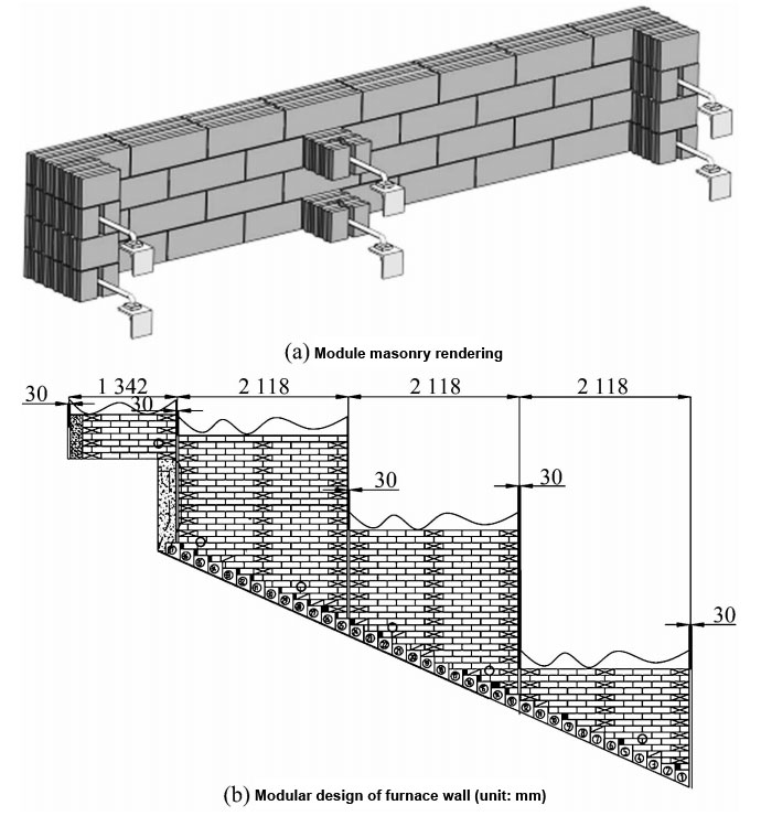
By classifying and designing refractory brick types and dimensions based on their specific functions, it is possible to standardize the bricks used in grate-fired furnaces. Furthermore, these standardized brick types can be utilized to implement a modular design for furnace walls. In practice, the furnace wall of an incinerator is composed of several modular units, each functioning as an independent yet interconnected component of the overall structure. This modular approach is well-suited for both the construction of new grate-fired furnaces and maintenance projects, offering simplified installation and high versatility.
For instance, a modular unit—consisting of a two-layer brick wall—can be constructed using a specific combination and arrangement of main bricks, staggered-joint bricks, adjustment bricks, end-cap bricks, and anchoring bricks (as illustrated in Figure 8(a)). Multiple such units can then be assembled to form the complete furnace wall, as shown in Figure 8(b). This strategy of optimizing brick types and employing modular design has been extensively applied in waste-to-energy incinerators both domestically and internationally.
The results indicate that, in addition to shortening production and maintenance cycles, the standardization of brick types and the modular design of furnace walls offer the following advantages:
- (1) The use of a multi-layer anchored modular design enhances structural anchoring, effectively resolving common issues such as thermal bulging or deformation of the furnace walls, thereby improving overall structural stability. In one waste-to-energy project utilizing a Hitachi grate-fired incinerator (with a daily processing capacity of 2 × 500 tons), the original furnace wall design required 74 different types of bricks, and the unit necessitated annual shutdowns for repairs due to bulging in the combustion zone. By implementing standardized brick types and a modular design, the number of required brick types was reduced to just five. The well-engineered multi-layer anchoring structure extended the service life of the furnace walls to over four years.
- (2) The modular nature of the furnace walls allows for the isolation of individual sections, enabling the implementation of air-cooled furnace wall structures in specific high-temperature zones. This air-cooling approach further lowers the temperature of the furnace walls, enhancing both their stability and the service life of the refractory materials. As shown in Figure 9, cooling air is used to cool the high-temperature furnace walls, absorbing heat in the process and typically reaching a temperature of 170–200°C. This heated air can either be fed directly into the furnace to support combustion or diverted outside the furnace before being reintroduced as secondary combustion air. For instance, in one waste-to-energy project utilizing a Mitsubishi-type grate incinerator, the original design required 260 different types of refractory bricks; through an optimized modular design, this number was reduced to just 13. Furthermore, the modules in the high-temperature zones were redesigned with an air-cooled structure, which significantly lowered the surface temperature of the refractory materials. This enhancement not only improved the stability of the furnace walls but also effectively inhibited the adhesion of fly ash to the wall surfaces. Consequently, the frequency of furnace shutdowns for ash removal decreased from once a month to once every four months, thereby reducing labor intensity and increasing the operational availability of the incinerator.
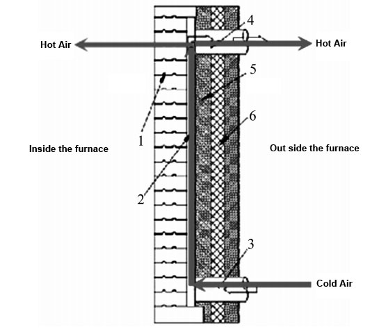
1—Working layer of refractory bricks; 2—Cooling air gap; 3—Air inlet; 4—Air outlet; 5—Thermal insulation layer; 6—Thermal barrier layer